The following was sent to me some time back... Hope this helps diagnose ABS problems!
The anti-lock brake system used on older Toyota Corolla models is essentially the same as that on the Camry, Celica and other Toyota models: A Bosch 2 non-integral design with four wheel speed sensors and a separate hydraulic control circuit for each wheel.
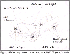
In 1992, the Corolla used a hydraulic modulator with four 3-position solenoid valves (the same as the Camry and Celica). The ABS control module was located under the instrument panel (See Fig. 1). Starting in 1993, the Corolla was equipped with a new hydraulic modulator (actuator) that has eight 2-position solenoid valves. The ABS control module is also mounted on the modulator assembly and can be replaced separately, if defective. The newer modulator also has a pump motor to recirculate fluid back to the master cylinder when brake pressure is being reduced during an ABS stop.
|
| Fig 1 |
Like other ABS systems, the eight solenoid valves in the ‘93 and newer modulator isolate, decrease or maintain brake fluid pressure in each individual wheel circuit as needed during an ABS stop. There are four inlet solenoid valves to isolate and hold pressure in each brake circuit, and four outlet solenoid valves to decrease pressure. The normal position of the inlet valves is open, while the normal position of the outlet valves is closed.
Each wheel has its own wheel speed sensor, and all are the traditional magnetic type that generate an AC signal that increases both frequency and amplitude with wheel speed. Sensors are removable but do not have an adjustable air gap.
TROUBLESHOOTING
Fortunately, Toyota provides flash codes to read the ABS codes on the Corolla. To check the codes, turn on the ignition, remove the short pin from the ABS check connector (See Fig. 2) and use a jumper to connect terminals Tc and E1.
 |
| Fig 2 |
If the ABS light blinks at a constant rate of two times per second, there are no fault codes stored in memory. That doesn’t necessarily mean everything is OK because something may be having an adverse affect on the operation of the ABS system. This includes low battery voltage, a "dirty" wheel speed sensor that is not giving a reliable reading or a hydraulic problem in the modulator assembly (See. Fig. 4).
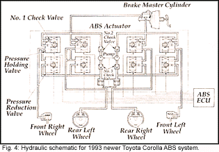 |
| Fig 4 |
If there are one or more stored codes in memory, the ABS will flash the first two-digit code, then the next and so on, repeating the code(s) as long as the check connector is jumped. The first number of flashes equals the first digit of the code. After a 1.5-second pause, the second number of flashes equals the second digit of the code. If there’s more than one code, there will be a 2.5 second pause before the next two-digit code flashes out.
TOYOTA ABS CODES12 — Short in solenoid relay circuit. Check modulator wiring harness, solenoid relay, solenoid relay wiring harness and solenoid relay connector.
13 — Open pump motor relay circuit. Check modulator wiring harness, pump motor wiring harness, pump motor relay circuit and pump motor connector.
14 — Short in pump motor relay circuit. Check modulator wiring harness, pump motor wiring harness, pump motor relay circuit and pump motor connector.
21 — Open or short in ABS solenoid for right front wheel.
22 — Open or short in ABS solenoid for left front wheel.
23 — Open or short in ABS solenoid for right rear wheel.
24 — Open or short in ABS solenoid for left rear wheel.
31 — Problem in right front wheel speed sensor circuit.
32 — Problem in left front wheel speed sensor circuit.
33 — Problem in right rear wheel speed sensor circuit.
34 — Problem in left rear wheel speed sensor circuit.
35 — Open in left front or right rear wheel speed sensor (WSS) circuit.
36 — Open in right front or left rear WSS circuit.
37 — Faulty rear speed sensor rotor.
41 — Battery voltage too low or high (under 9.5 volts or over 16.2 volts). Check battery and charging system.
51 — Pump motor is locked or pump motor circuit is open. Check pump motor, motor relay, wiring harness and modulator ground connections.
"Always on" (no flash codes, just a steady light) — Malfunction of ABS module.
To clear fault codes, leave the jumper in place between terminals Tc and E1 with the key on, then pump the brake pedal eight or more times in three seconds or less. When codes are erased, the ABS light should flash two times per second.
SPECIAL WSS TEST MODE
If you’ve found a fault code for a wheel speed sensor, it may be due to an
open or short in the sensor’s wiring harness, physical damage to the sensor or
sensor ring, a buildup of metallic debris on the sensor tip or corrosion.
Toyota provides a special wheel speed sensor diagnostic procedure that can generate additional codes to help you diagnose the underlying fault. Though this test is really redundant, it may help you isolate a troublesome wheel speed sensor.
To enter the special WSS test mode, turn off the ignition. Leave the short pin in the ABS check connector and use a jumper wire to connect terminals Ts and E1. Engage the parking brake and start the engine. If the system is in the special diagnostic mode, the ABS light will flash at a rate of four times per second.
Drive the vehicle straight ahead at a speed above 50 mph. The ABS light will stop blinking as soon as you exceed 28 mph, then blink once when you hit 50 mph. As soon as you’ve seen the blinks, the test is complete and you can stop the vehicle.
To retrieve the wheel speed sensor codes, use the same diagnostic procedure that you would use to read the normal ABS codes. Remove the short pin from the ABS check connector and jump Tc to E1. If a problem was detected in any of the wheel speed sensor circuits, you’ll find one or more of the following codes:
71 — Low voltage in right front WSS circuit.
72 — Low voltage in left front WSS circuit.
73 — Low voltage in right rear WSS circuit.
74 — Low voltage in left rear WSS circuit.
75 — Abnormal signal from right front speed sensor. Check the sensor ring on the right front brake rotor for damage or debris.
76 — Abnormal signal from the left front speed sensor. Check the sensor ring on the left front brake rotor for damage or debris.
77 — Abnormal signal from the right rear speed sensor. Check the sensor ring on the right rear brake.
78 — Abnormal signal from the left rear speed sensor. Check the sensor ring on the left rear brake.
Light blinks four times a second — No problem found. All speed sensors are reading normal.
WSS CHECKS
To measure a wheel speed sensor’s output voltage and circuit continuity at
the same time, plug a breakout box into the ABS module’s wiring harness and
attach the test leads from a DVOM to the appropriate sensor circuit pins on the
breakout box. (Note: The DVOM test leads can also be connected directly to the
wheel speed sensor, but testing the sensor this way won’t show if the signal is
getting through to the ABS control module or not.) Spin the wheel by hand and
note the sensor’s voltage reading during that time.
A good wheel speed sensor will generally produce an alternating current (AC) voltage reading of 50 to 700 MV when the wheel is spun at a speed of about one revolution per second.
If the voltage reading is low or nonexistent, check the sensor’s resistance (with the key off). This can be done through the breakout box with the DVOM. Checking resistance through the breakout box will tell you if the sensor’s wiring harness is OK. If the wheel speed sensor doesn’t read between 990 to 1210 ohms, disconnect the sensor from its wiring harness and check the sensor’s resistance by attaching the DVOM test probes to the sensor leads. A resistance reading that’s now within range tells you the problem is in the wiring, not the sensor. If the sensor has too much internal resistance (opens) or too little resistance (shorts), the sensor is defective and needs to be replaced.
Grounds or shorts in the wheel speed sensor cables can be found by checking continuity between the wiring connectors. (See Fig. 3). If a defect is found in the wires that run between the sensor and the chassis, replacing the wires with new ones is a better repair choice than trying to fix or splice them. These wires undergo a great deal of flexing every time the suspension encounters a bump, so new wires will hold up better than ones that have been soldered, spliced or taped.
Another way to check wheel speed sensors is with an oscilloscope. By displaying the sensor’s output pattern graphically on the scope screen, you can often see problems that are difficult to find otherwise. A missing or damaged tooth on a sensor ring, for example, may not produce a noticeable change in the sensor’s output voltage. Yet, the fluctuation that occurs in the signal every time the missing tooth passes under the tip of the sensor may be enough to affect the operation of the ABS module.
The scope connection can either be made through the breakout box or it can be hooked up directly to the wheel speed sensor. A scope pattern for a wheel speed sensor should show a classic sine wave alternating current pattern that changes both in frequency and amplitude with wheel speed. As the wheel is turned faster, both signal frequency and amplitude should increase. Damaged or missing teeth on the sensor ring will show up as flat spots or gaps in the sine wave pattern. A bent axle or hub will produce an undulating pattern that changes as the strength of the sensor signal changes with every revolution.
If the scope pattern produced by the sensor is flattened (diminished amplitude) or erratic, it usually indicates a weak signal caused by an excessively wide air gap between the tip of the sensor and its ring, or a build up of metallic debris on the end of the sensor. A weak signal can also be caused by internal resistance in the sensor or its wiring circuit, or loose or corroded wiring connectors.